0121.5–32"
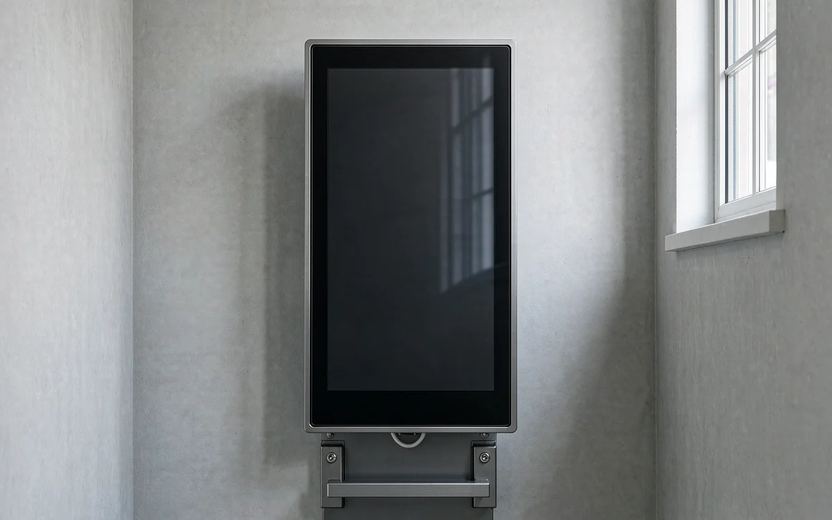
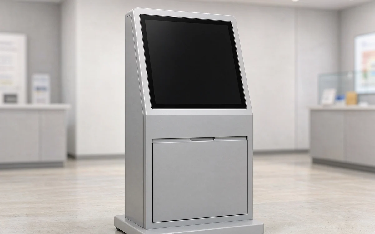
Freestanding
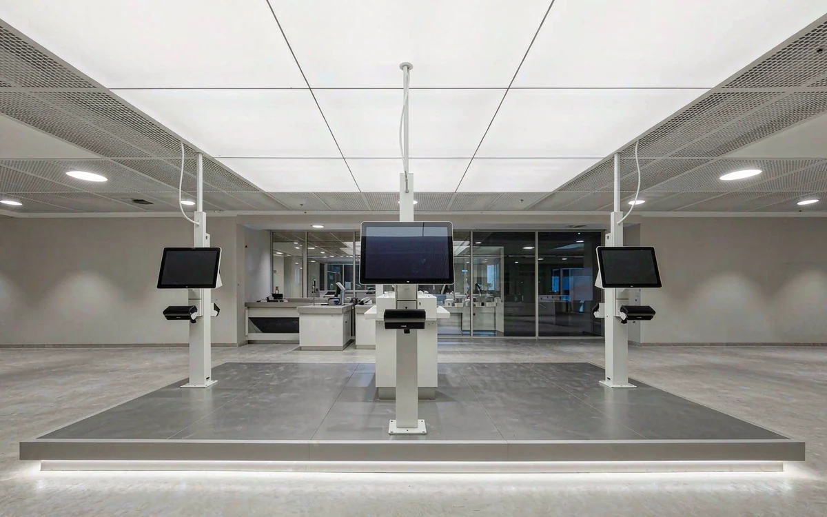
Check-in, queueing and information points with a stable floor base and a front-service bay.
View series
SELF-SERVICE / LAYOUT DEMO 03
Self-service terminals designed, fabricated and assembled as one system — so the touchscreen, printer, payment module and housing actually fit together.
Screen size, peripheral list, installation environment and target volume decide the enclosure.
TERMINAL TYPES
The enclosure changes; the mounting pattern, service access and peripheral bay stay consistent across the range.
Screen size follows the interaction; the enclosure follows where the unit stands; the bay follows the peripheral list.
Check-in, queueing and information points with a stable floor base and a front-service bay.
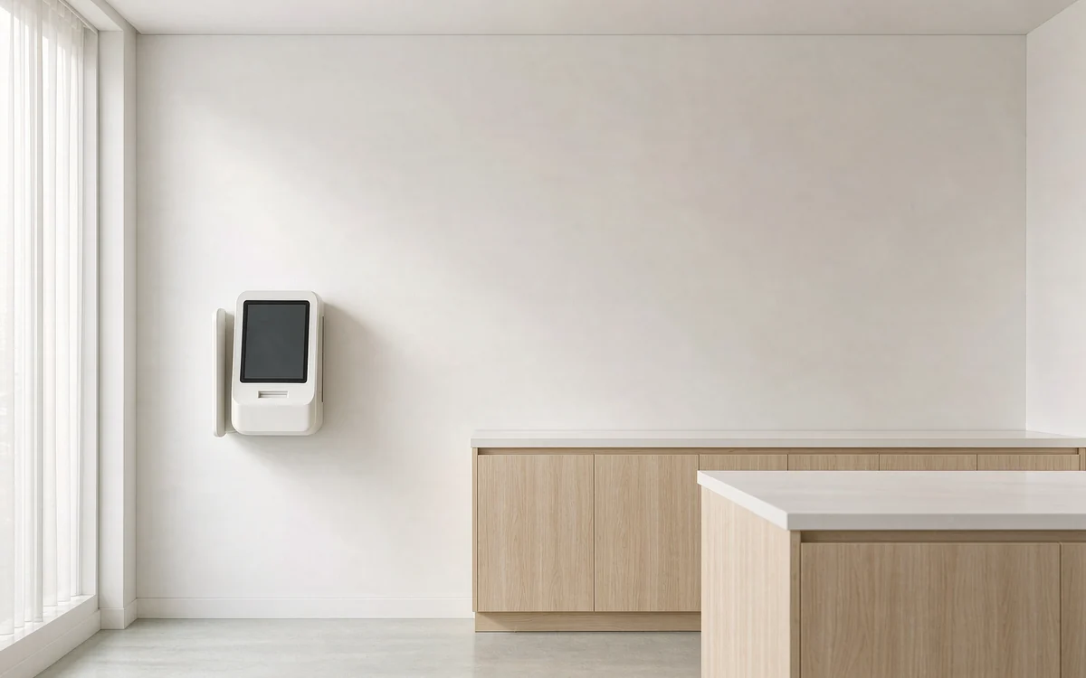
Slim units for corridors, elevators and limited floor space, with a fixed wall bracket.
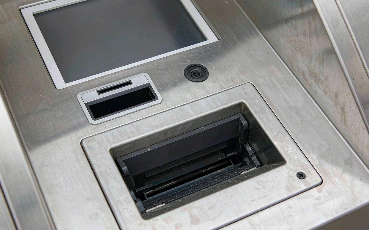
Card, QR and receipt modules in a serviceable front bay with a separated payment zone.
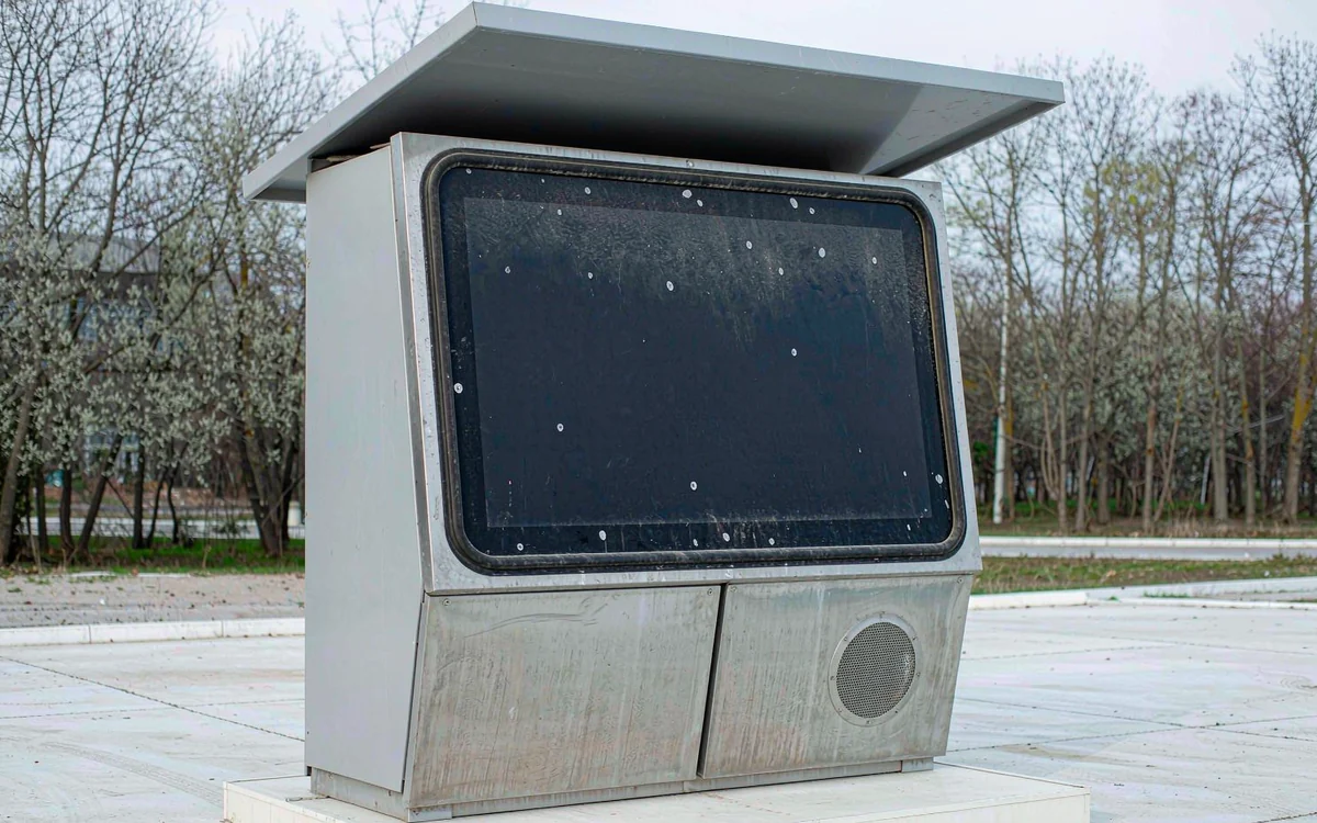
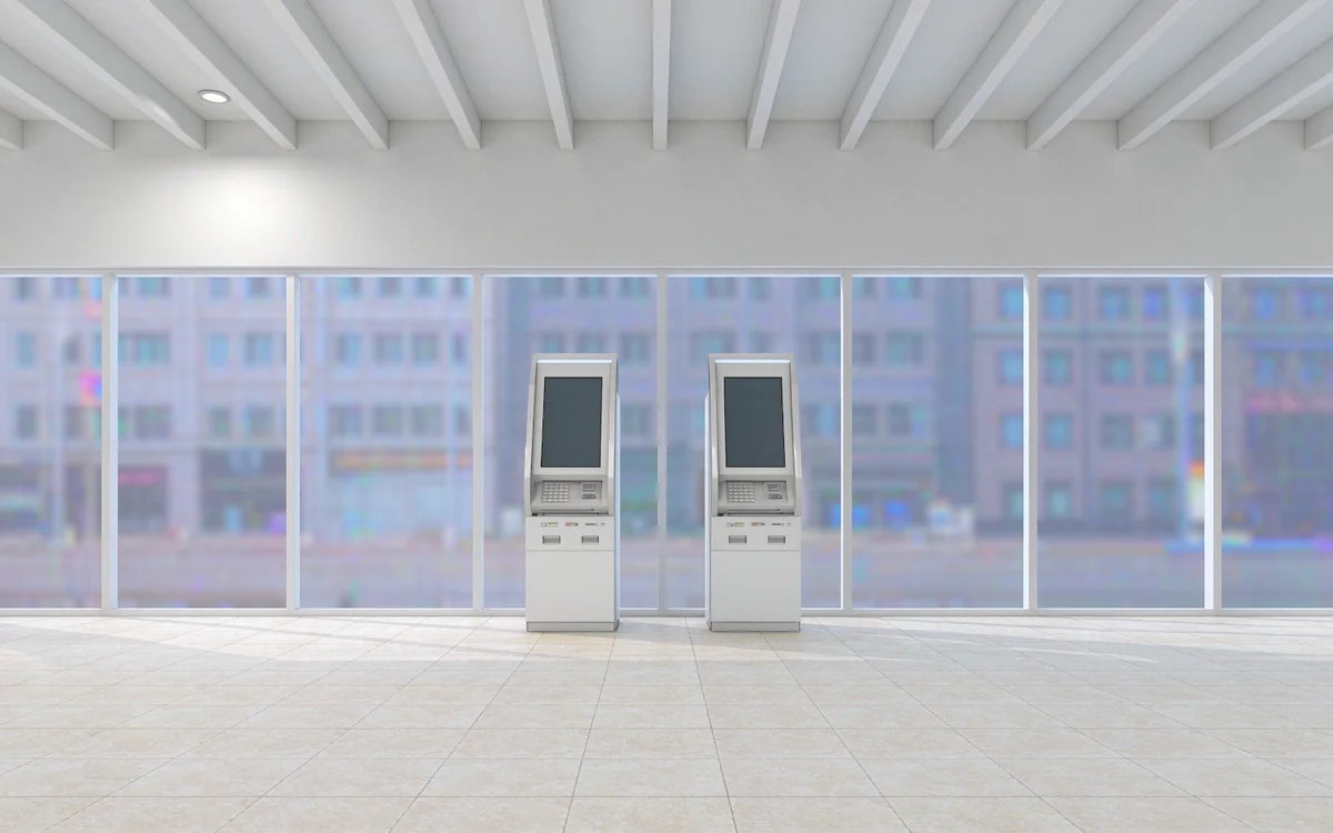
Sealed housings with thermal management, high-bright displays and a sheltered mounting plan.
INSIDE THE ENCLOSURE
What is worth checking before an enclosure drawing is signed off: how peripherals mount, where heat goes, how cables run and how a technician reaches them.
Service access decides the wall clearance. Decide it during industrial design, not after the housing is tooled.
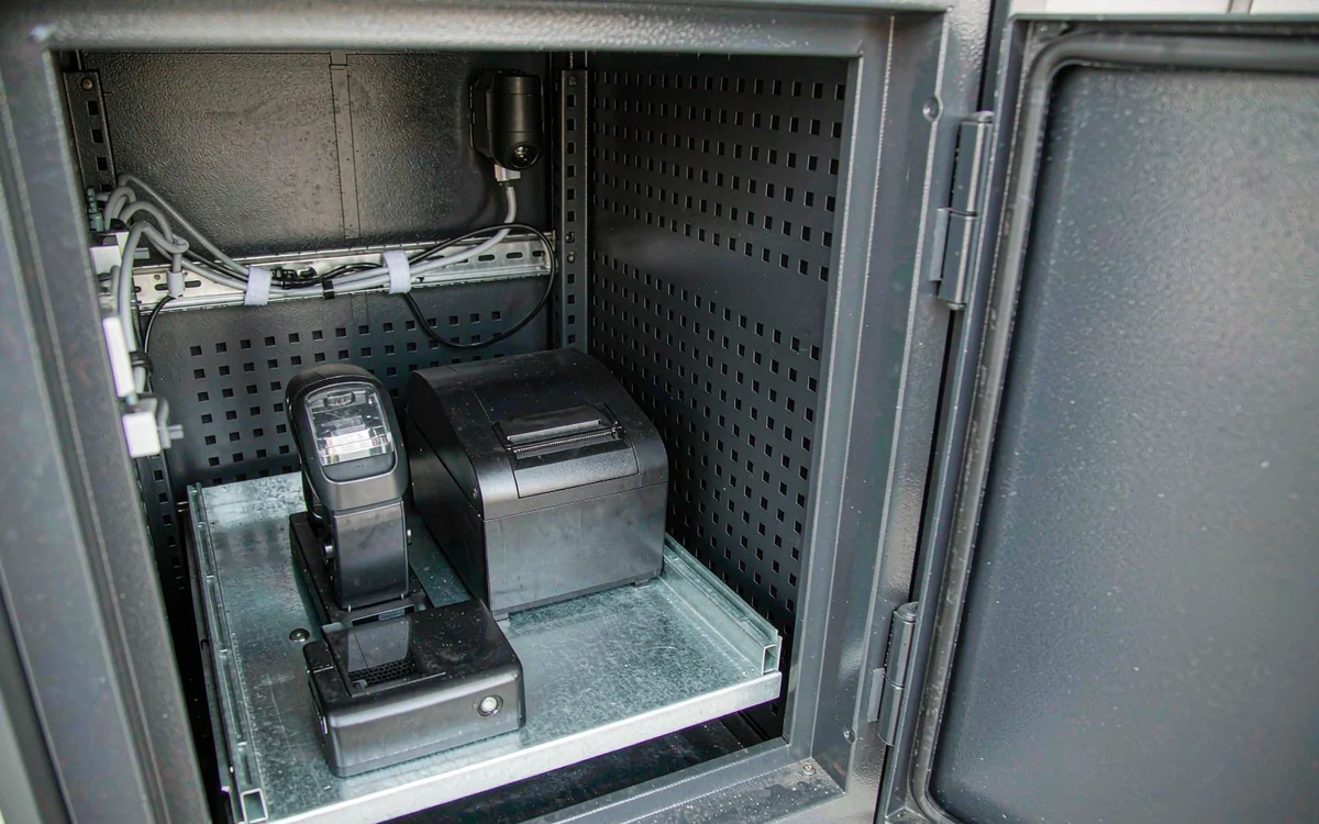
Printer, scanner, card reader and QR window on one removable tray.
Airflow, filtered intakes and the high-bright panel heat load.
Separated power, data and payment looms with labelled termination points.
Floor base, wall bracket or sheltered plinth with the same fixing grid.
DEPLOYMENTS
Four common placements. The enclosure changes; the peripheral bay stays reachable from the front.
Each placement changes one dominant requirement. Find that first and the rest of the build follows.
Self-checkout and queue busting with scanner, payment and receipt modules in one bay.
Ticketing and information units with high-bright displays and a sealed front panel.
Check-in, form capture and queue management with privacy screening and a card reader.
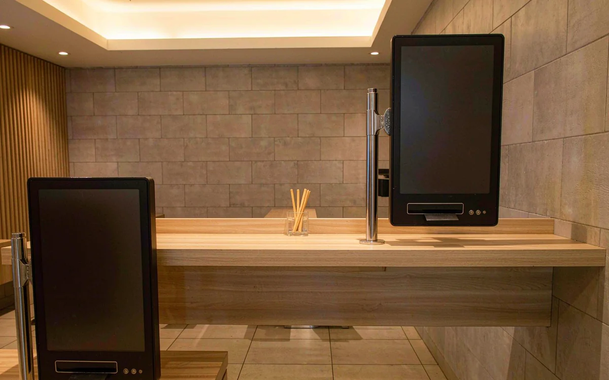
Order and payment points with a receipt printer and a wipeable front surface.
PLATFORM COMPARISON
Read across a row to see what changes between form factors. These are platform ranges, not a substitute for an enclosure drawing.
Start with the peripheral list, then the installation environment, then the target volume.
PLATFORM RANGES
Indicative platform ranges, not a promise for any individual model. A real quotation starts with the peripheral list.
Every range here narrows once the modules, the environment and the volume are known.
DEPLOYMENT CONTEXT
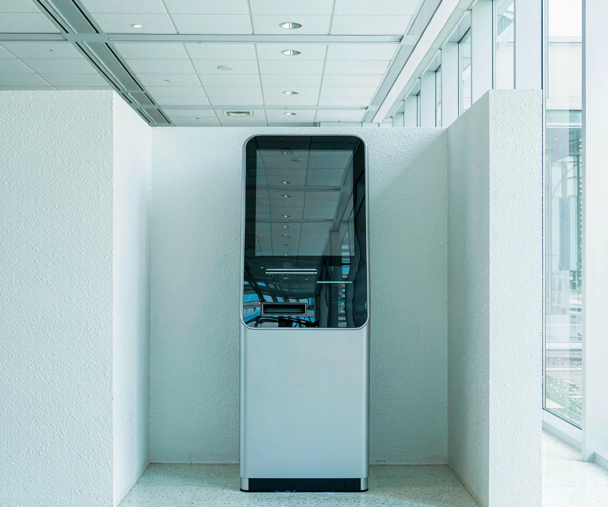
Application references shown as illustrative photography. Each frame isolates a different constraint on the specification.
These are illustrative application images, not photographs of completed projects.
CAPABILITIES
For an engineering buyer, the production boundary matters more than a product render. Four stages, all under one roof.
Burn-in and I/O results are logged against unit serial numbers, so a later service call can be matched.
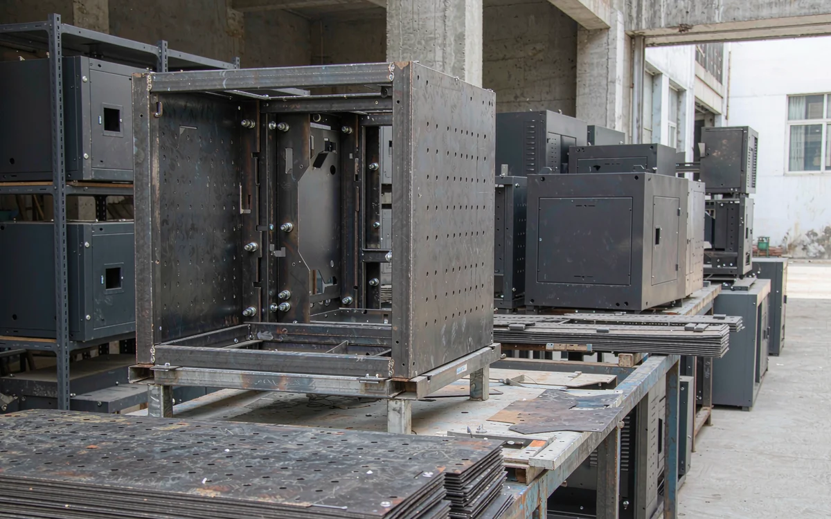
Laser cutting, CNC bending, welding and powder coating of the enclosure.
ESD-controlled lines with a documented work instruction per model.
Display, touch, printer, scanner and payment module fit-out in one bay.
Burn-in, touch accuracy and I/O checks logged by serial number.
WHAT SHIPS WITH IT
A terminal is a system with drawings and spares. This is the delivery file a field technician actually works from.
Ask for these four documents before the crate leaves; they are what make a later service visit straightforward.
Fixing grid, service clearances and the front-bay layout on one sheet.
Peripherals, looms and labelled termination points with quantities.
Burn-in, touch accuracy and I/O results matched to each unit.
Printers, readers, fans and filters listed against the build.
CUSTOMISATION
Four steps, each with something you can approve before the next one starts.
Every step ends with a drawing or a working unit, rather than a status update.
Peripherals, environment, mounting, brand surface and target volume.
Enclosure drawing, service access and thermal plan for sign-off.
A working unit for fit, firmware and ergonomics review.
Small batch with assembly docs and a test record per serial.
BEFORE YOU ASK
Short answers to the six things that usually decide a terminal build. The full answers live in the build guide.
A peripheral list is usually faster than a long email thread.
Yes within the same bay pattern. Printers, scanners and readers share the fixing grid, so the tray can be changed without retooling the housing.
Only above the stated thermal load. A sheltered IP54 unit with filtered airflow covers most placements; direct sun is checked separately.
A working prototype comes first, then a pilot batch with assembly docs. Volume is agreed before tooling, not after.
Colour, powder-coat finish and the front panel print area are specified at industrial design, before the sheet metal is cut.
Every unit runs a burn-in and I/O check, and the result is logged against its serial number in the delivery file.
Integration covers display, touch, drivers and peripherals. Application software and payment certification stay with the client's own stack.
DOCUMENTS
Three sample documents a buyer usually asks for before an enclosure discussion. Shown here as layout placeholders.
These are placeholders in a demo layout, not downloadable files.
Fixing grid, service clearance and front-bay layout in one sheet.
View sampleWhich modules fit which bay, with power and data notes.
View sampleAssembly docs, test records and spares to confirm before a batch.
View sampleSTART A BUILD
Screen size, modules, installation environment and expected volume are enough for a first enclosure proposal.
Request a proposalThis is a layout demo. No enquiry is actually sent.